operational coordinates (task coordinates)
The Basics
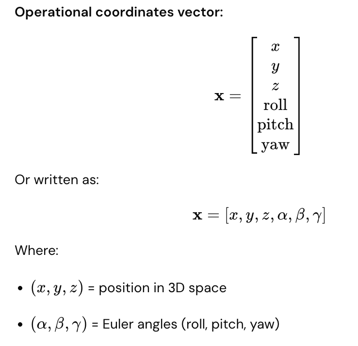
Operational coordinates (also called task coordinates) describe where the end-effector is and which way it's pointing in 3D space. Unlike generalized coordinates (joint angles), these specify the robot's actual location and orientation in the world.
Simple analogy: Generalized coordinates = robot's internal shape; Operational coordinates = robot's hand position and direction in space.
The 6 Parameters (6D Space)
Position (3 parameters)
Where the end-effector is located:
- X = left/right
- Y = forward/backward
- Z = up/down
Z (up)
↑
│ Y (forward)
│ /
│ /
└──────→ X (right)
Orientation (3 parameters)
Which way the end-effector is pointing:
- Roll = rotation around X-axis (like rolling an airplane wing)
- Pitch = rotation around Y-axis (like pitching an airplane nose up/down)
- Yaw = rotation around Z-axis (like turning an airplane left/right)
Roll (rotation around X): Pitch (rotation around Y): Yaw (rotation around Z):
╱╲ ▲
╱ ╲ ←twist ╱ ←tip up/down ↻ ←turn left/right
╱ ╲ │
Complete 6D Representation
Real-World Example
Robot gripper picking up a box:
Current operational coordinates:
x = 0.5 m (right of base)
y = 0.3 m (forward)
z = 0.8 m (0.8 m above ground)
Roll = 0° (gripper level)
Pitch = 0° (gripper horizontal)
Yaw = 45° (gripper rotated 45° around vertical axis)
This completely describes:
- Where the gripper is in space
- How the gripper is oriented
- What angle it's approaching the box from
Generalized vs. Operational Coordinates
Aspect | Generalized (q) | Operational (x) |
What it describes | Robot's internal shape | End-effector in world |
For 3-DOF arm | [θ₁, θ₂, θ₃] | [x, y, z, roll, pitch, yaw] |
Domain | Joint space | Cartesian/Task space |
What you command | "Move joint 1 to 45°" | "Move gripper to (0.5, 0.3, 0.8)" |
Intuitive? | Less intuitive | More intuitive (like giving directions) |
Generalized Coordinates Operational Coordinates
(Robot internal) (End-effector in world)
q = [45°, 30°, 60°] → x = [0.5m, 0.3m, 0.8m, 0°, 0°, 45°]
(joint angles) (position + orientation)
Practical Robot Programming
Two ways to command movement:
Joint Space (Generalized Coordinates)
move_joint(joint=1, angle=45°)
move_joint(joint=2, angle=30°)
move_joint(joint=3, angle=60°)
- Direct motor commands
- Fast, simple
- Not intuitive for humans
Task Space (Operational Coordinates)
move_to_position(x=0.5m, y=0.3m, z=0.8m)
set_orientation(roll=0°, pitch=0°, yaw=45°)
- Intuitive (like giving directions)
- Controller calculates required joint angles
- Requires inverse kinematics computation
Orientation Representations
Besides Euler angles (roll, pitch, yaw), alternatives exist:
Rotation Matrix
3×3 matrix describing orientation (9 values, but constrained)
Quaternion
4 values $(q_w, q_x, q_y, q_z)$ representing rotation
- More compact than matrices
- Better for interpolation
- Less prone to singularities
Axis-Angle
Rotation axis + angle of rotation
- Intuitive
- Fewer parameters
All representations describe the same thing: end-effector orientation.
Workspace Visualization
Operational coordinates define the robot's workspace:
3D workspace of robot:
All reachable (x, y, z) positions
form a 3D volume
Z
↑
╱───────╲
│ Robot │ ← Reachable space
│Workspace│
╲───────╱
└──→ X, Y
For a 6-DOF arm:
- Can reach any position within workspace
- Can point gripper in any direction at that position
Real-World Task Example
Robot assembly task:
Task: Screw bolt into hole
Operational coordinates needed:
1. Position gripper at hole: (0.5m, 0.3m, 0.8m)
2. Orient gripper straight down: (0°, 0°, 0°)
3. Apply force while rotating: yaw = continuous rotation
Controller translates to:
q(t) = [θ₁(t), θ₂(t), θ₃(t), θ₄(t), θ₅(t), θ₆(t)]
Each joint angle updates continuously to maintain
desired operational coordinates.
Singular Points (Singularities)
Problem: Some positions have singularities
At a singularity:
- Small change in position requires huge joint movements
- Inverse kinematics becomes ill-defined
- Robot loses control in some direction
Example: Fully extended arm trying to move straight ahead
Engineers avoid singularities when planning operational tasks.
Advantages and Disadvantages
Operational Coordinates Advantages
✓ Intuitive (human-friendly) ✓ Easy to specify tasks ✓ Directly related to physical goals ✓ Good for visualization
Operational Coordinates Disadvantages
✗ Requires inverse kinematics calculation ✗ Singularities exist ✗ Not unique (multiple joint angles can reach same position) ✗ Slower computation
Generalized Coordinates Advantages
✓ Direct motor commands ✓ No singularities ✓ Unique representation ✓ Fast computation
Generalized Coordinates Disadvantages
✗ Not intuitive ✗ Hard to visualize ✗ Difficult to specify desired tasks
Key Comparison Table
Parameter | Meaning | Example |
x | Lateral position | 0.5 m right of base |
y | Forward/backward position | 0.3 m forward |
z | Height | 0.8 m above ground |
Roll | Twist around forward axis | 0° (level) |
Pitch | Tilt up/down | -90° (pointing down) |
Yaw | Turn left/right | 45° (rotated) |
Trajectory Planning
Operational coordinates are easier for planning smooth paths:
Trajectory from A to B in operational space:
Point A: [0.2m, 0.1m, 0.5m, 0°, 0°, 0°]
Point B: [0.6m, 0.4m, 0.9m, 0°, 0°, 45°]
Smooth interpolation between A and B
Then convert entire trajectory to generalized coordinates
Key Takeaway
Operational coordinates are the "world view" of the robot—they describe where the end-effector actually is in 3D space and how it's oriented. Six parameters (3 for position, 3 for orientation) fully specify the end-effector pose. While less intuitive for computation than joint angles, operational coordinates are much more intuitive for task specification. Converting between operational and generalized coordinates via kinematics is fundamental to robot programming and control.